nuovo blog
I materiali termoplastici rinforzati con fibre lunghe (LFRT) sono sempre più utilizzati in applicazioni di stampaggio a iniezione dove sono richieste elevate prestazioni meccaniche. Sebbene la tecnologia LFRT possa offrire eccellente resistenza, rigidità e resistenza all'impatto, il metodo di lavorazione gioca un ruolo critico nel determinare le prestazioni finali che un pezzo stampato può raggiungere.
Per stampare con successo gli LFRT, è essenziale comprendere alcune delle caratteristiche uniche di questi materiali. Riconoscere le differenze tra LFRT e i termoplastici rinforzati convenzionali ha guidato lo sviluppo di attrezzature specializzate, design di pezzi e stampi, e tecniche di lavorazione per massimizzare il valore e il potenziale prestazionale degli LFRT.
Per preservare la lunghezza delle fibre durante lo stampaggio a iniezione di LFRT, è necessario considerare tre aree chiave:la pressa a iniezione, il design del pezzo e dello stampo, e le condizioni di lavorazione.
La differenza principale traLFRTe i composti convenzionali rinforzati con fibre di vetro corte o tagliate èla lunghezza della fibra. Negli LFRT, le fibre hanno tipicamente la stessa lunghezza dei granuli. Questo perché la maggior parte dei materiali LFRT viene prodotta utilizzando un processo di pultrusione anziché una miscelazione basata sul taglio (shear-based compounding).
Durante la produzione di LFRT, fasci continui di roving di fibra di vetro non ritorti vengono prima tirati attraverso una filiera, dove vengono rivestiti e impregnati con resina. Dopo essere usciti dalla filiera, il filo di plastica rinforzata continua viene tagliato o granulato, tipicamente in lunghezze di 10–12 mm. Al contrario, i composti convenzionali in fibra di vetro corta contengono fibre tritate che sono tipicamente lunghe 3–4 mm, e la loro lunghezza può essere ulteriormente ridotta a meno di 2 mm durante la lavorazione in un estrusore basato sul taglio.
La maggiore lunghezza della fibra nei granuli LFRT aiuta a migliorare le prestazioni meccaniche, in particolare la resistenza all'impatto e la tenacità, mantenendo al contempo la rigidità. Finché le fibre mantengono la loro lunghezza durante lo stampaggio, formano uno “scheletro interno” all'interno del materiale, fornendo prestazioni meccaniche eccezionalmente elevate.
Tuttavia, pratiche di stampaggio inadeguate possono trasformare efficacemente un materiale a fibra lunga in un materiale a fibra corta. Se la lunghezza della fibra viene ridotta significativamente durante la lavorazione, non è possibile raggiungere il livello di prestazioni desiderato.
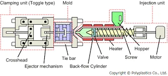
Una delle domande più frequenti sullalavorazione LFRTè se le attrezzature di stampaggio a iniezione esistenti possano essere utilizzate per stampare questi materiali. Nella maggior parte dei casi, le attrezzature progettate per la lavorazione di composti rinforzati con fibre corte possono essere utilizzate anche per gli LFRT. Sebbene le attrezzature standard per lo stampaggio di fibre corte siano adeguate per la maggior parte dei pezzi e prodotti LFRT, alcune modifiche alle attrezzature possono aiutare a preservare meglio la lunghezza della fibra durante la lavorazione.
Una vite per uso generale con la tipica configurazionealimentazione-compressione-dosaggioè ben adatta a questo processo. Ridurre il rapporto di compressione nella sezione di dosaggio può aiutare a minimizzare il taglio che potrebbe danneggiare le fibre.
Un rapporto di compressione della sezione di dosaggio di circa 2:1 è considerato ottimale per i prodotti LFRT. Generalmente non c'è bisogno di utilizzare leghe metalliche speciali per la vite, il cilindro o altri componenti, poiché gli LFRT causano meno usura rispetto ai termoplastici rinforzati con fibra di vetro corta convenzionali.
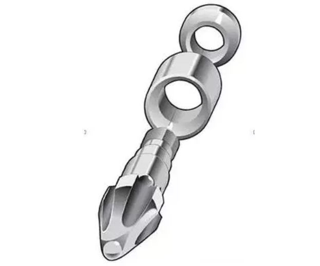
Un altro componente che potrebbe beneficiare di una revisione del design è lapunta dell'ugello. Alcuni materiali termoplastici sono più facili da lavorare con una punta dell'ugello a cono rovesciato, che genera un alto livello di taglio mentre il materiale viene iniettato nella cavità dello stampo. Tuttavia, questo tipo di punta dell'ugello può ridurre significativamente la lunghezza della fibra dei compositi rinforzati con fibre lunghe.
Inoltre, le aperture dell'ugello e del canale di colata dovrebbero essere generosamente dimensionate, con un diametro di almeno5.5 mm (0.250 in.), e non dovrebbero presentare spigoli vivi. È importante capire come il materiale scorre attraverso l'attrezzatura di stampaggio a iniezione e identificare le aree in cui un taglio eccessivo può causare la rottura delle fibre.
Un corretto design del pezzo e dello stampo può anche svolgere un ruolo importante nel preservare la lunghezza della fibra negli LFRT. Eliminare gli angoli vivi attorno alle caratteristiche del pezzo, inclusi nervature, bossoli e altri dettagli, può aiutare a prevenire stress inutili nel pezzo stampato e ridurre il danneggiamento delle fibre.
I componenti dovrebbero utilizzare un design con spessore nominale della parete con uno spessore della parete relativamente uniforme in tutto il pezzo. Grandi variazioni nello spessore della parete possono portare a un riempimento incoerente e a un orientamento indesiderato delle fibre all'interno del componente.
Laddove siano necessarie sezioni più spesse o più sottili, è necessario evitare cambiamenti improvvisi nello spessore della parete. Tali transizioni possono creare aree ad alto taglio che possono danneggiare le fibre e diventare fonti di concentrazione degli sforzi. Come regola generale, cercare di posizionare il punto di iniezione nella sezione più spessa e consentire al materiale di fluire verso la sezione più sottile, in modo che la fine del riempimento si trovi nell'area più sottile.
Le linee guida generali per la progettazione di materie plastiche raccomandano di mantenere lo spessore della parete al di sotto di 4 mm (0,160 in.) per favorire un flusso uniforme e regolare e ridurre la probabilità di segni di ritiro e vuoti. Per i composti LFRT, lo spessore ottimale della parete è solitamente di circa 3 mm (0,120 in.), con uno spessore minimo di circa 2 mm (0,080 in.).
Il componente stesso è solo un aspetto della progettazione. È altrettanto importante considerare come il materiale entra nello stampo. Un danno significativo alle fibre può verificarsi nelle aree del canale di colata e del punto di iniezione se queste caratteristiche non sono progettate correttamente per guidare il materiale nella cavità.
Durante la progettazione di uno stampo per composti LFRT, sono preferibili canali di colata a sezione circolare, con un diametro minimo di 5,5 mm (0,250 in.). Qualsiasi design del canale di colata diverso da una configurazione a sezione circolare presenterà angoli che possono aumentare lo stress durante lo stampaggio e danneggiare il rinforzo in fibra di vetro. I sistemi a canale caldo con punti di iniezione aperti sono accettabili.
Lo spessore minimo del punto di iniezione dovrebbe essere 2 mm (0,080 in.). Ove possibile, posizionare il punto di iniezione lungo un bordo che non ostruisca il flusso del materiale nella cavità. Per i punti di iniezione situati sulla superficie del componente, potrebbe essere necessaria una curva a 90° per evitare la rottura delle fibre e la conseguente riduzione delle prestazioni meccaniche.
Infine, occorre prestare attenzione alla posizione delle linee di giunzione e a come queste possano influenzare le aree del componente che saranno soggette a carichi o sollecitazioni durante l'esercizio. Un corretto posizionamento del punto di iniezione dovrebbe essere utilizzato per spostare le linee di giunzione in aree in cui sono previsti livelli di sollecitazione inferiori.
L'analisi computerizzata del riempimento dello stampo può aiutare a determinare dove saranno localizzate queste linee di giunzione. L'analisi strutturale agli elementi finiti (FEA) può quindi essere utilizzata per confrontare le aree ad alta sollecitazione con le posizioni delle linee di giunzione identificate tramite l'analisi del riempimento dello stampo.
Va notato che queste linee guida per la progettazione di componenti e stampi sono raccomandazioni piuttosto che requisiti assoluti. Esistono molti esempi di componenti con pareti sottili, variazioni nello spessore della parete e caratteristiche complesse o sottili che hanno ottenuto buone prestazioni utilizzando composti LFRT.
Tuttavia, più un design si discosta da queste raccomandazioni, maggiore potrebbe essere il tempo e l'impegno necessari per garantire che vengano raggiunti tutti i vantaggi della tecnologia a fibra lunga.
Condizioni di processo adeguate sono fondamentali per il successo dello stampaggio di LFRT. Con i giusti parametri di processo, è possibile produrre componenti LFRT di alta qualità utilizzando una pressa a iniezione per uso generale e uno stampo progettato correttamente.
In altre parole, anche con attrezzature e un design dello stampo idonei, condizioni di processo scadenti possono comunque causare danni alle fibre e perdita della lunghezza delle stesse. Ciò rende essenziale comprendere cosa incontreranno le fibre durante il processo di stampaggio e identificare le aree in cui può verificarsi un taglio eccessivo.
Innanzitutto, contropressione deve essere monitorata attentamente. Una contropressione eccessiva introduce elevate forze di taglio nel materiale, che possono ridurre la lunghezza delle fibre. Si consiglia di iniziare con una contropressione pari a zero e di aumentarla solo quanto necessario per garantire che la vite si ritragga in modo costante durante la plastificazione.
Una contropressione di circa 1,5–2,5 bar (20–50 psi) è generalmente sufficiente per ottenere un'alimentazione costante.
Anche velocità elevate della vite possono avere un effetto negativo. Più velocemente ruota la vite, maggiore è la probabilità che materiale solido o non sufficientemente fuso entri nella sezione di compressione della vite, causando potenzialmente danni alle fibre.
Analogamente alla raccomandazione per la contropressione, la velocità della vite deve essere mantenuta il più bassa possibile, garantendo comunque un recupero della vite stabile e costante. Una velocità della vite di 30–70 giri/min viene comunemente utilizzata durante lo stampaggio di composti LFRT.
Durante lo stampaggio a iniezione, la fusione avviene attraverso gli effetti combinati di taglio e calore. Poiché l'obiettivo durante la lavorazione di LFRT è proteggere la lunghezza delle fibre riducendo al minimo il taglio, è generalmente richiesto più calore. A seconda del sistema di resina, la temperatura di lavorazione per i composti LFRT è tipicamente 10–30°C superiore a quella utilizzata per i composti rinforzati convenzionali.
Prima di aumentare semplicemente le temperature del cilindro in tutta la macchina, occorre prestare attenzione al profilo di temperatura del cilindro inverso. In condizioni normali, le temperature del cilindro aumentano man mano che il materiale si sposta dalla tramoggia verso l'ugello. Per LFRT, tuttavia, si raccomanda una temperatura più elevata in corrispondenza della tramoggia.
Questo profilo di temperatura inverso aiuta ad ammorbidire e fondere i granuli di LFRT prima che entrino nella sezione di compressione ad alto taglio della vite, il che aiuta a preservare la lunghezza delle fibre.
L'ultima considerazione sulla lavorazione riguarda l'uso di materiale di recupero. La macinazione di parti stampate o materozze comporta solitamente lunghezze delle fibre inferiori, pertanto l'aggiunta di materiale di recupero può influire sulla lunghezza complessiva delle fibre del materiale.
Parlaci della tua applicazione, delle prestazioni meccaniche richieste, del sistema di resina, del contenuto di fibre e del metodo di lavorazione. Il nostro team può aiutarti a valutare le soluzioni termoplastiche rinforzate con fibre lunghe più adatte.
Seguici :


-- ricevi aggiornamenti con gli ultimi argomenti

 e-mail
 italiano
 English
 français
 Deutsch
 русский
 español
 português
 العربية
 日本語
日本語 한국의
한국의 中文
中文